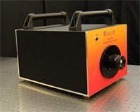
AXIS-NV: High Dynamic Range Streak Camera
AXIS-NV SPECIFICATIONS
STREAK TUBE
This streak camera uses a P510 PHOTONIS streak tube built according to high quality standards and features:
- 10-50 picosecond time resolution
- High spatial resolution
- Wide slit (35mm x 5mm)
- Ruggedized for harsh environment
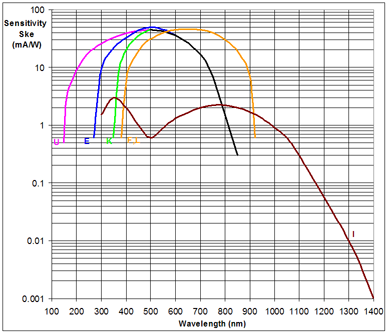
It can be built with different cathodes and matched with the experiment for optimal throughput:
SPATIAL RESOLUTION
Photocathode length (X): 35 mm
Photocathode effective width (Y): adjustable from 50 µm to 5 mm
Spatial Resolution (dx): 60µm or 30µm with 50% contrast at the center of the screen
Number of spatial resolution units in screen (X/dx): 500 0r 1000 points
TIME RESOLUTION
Available Ranges (ΔT): 2 ns to 1 ms
Number of time-resolution units in screen (Nt): 600 in narrow slit mode
Single-shot time resolution (δt): δt = ΔT / Nt 5 ps or 150 ps
TRIGGER
| Standard Sweep Unit | |
| Trigger pulse | Electrical |
| Requirements | 5-10 V in 50Ω |
| Maximum repetition rate | 1000 kHz |
| Jitter | < 15 ps RMS |
READOUT
Readout type: TE-Cooled CCD Digital camera
CCD chip size: 4096 x 4096 pixels
Digitizer: 16 bit
Coupling to streak tube: 1.4:1 Fiber optic taper
OPERATION MODES
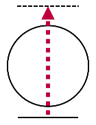 |
Normal sweep The sweep crosses the whole screen and ends outside. |
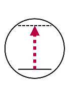 |
Timing mode The sweep always remains in the screen. It is used to synchronize the streak camera to the experiment. |
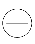 |
Focus mode The slit image is positioned at the center of the screen. The sweep trigger is disabled. This mode is used to align the experimental setup and to adjust the incident light level. |
INTERNAL COMPUTER and SOFTWARE
AXIS-NV is an all-in-one system that is operated locally by connecting a monitor, a keyboard and a mouse.
It comes with an internal computer that controls the streak tube supplies, the sweep circuits, monitors voltage stability, performs different self tests and safety checks. It can also control other optional peripherals via the USB port (a laser system, for example).
All required software comes pre-installed on the system. It is used to:
- Control whole system and acquire images
- Control the laser system (optional)
- Plot lineouts along time axis or space axis
- save image in different formats
Remote control over Gigabit Ethernet :
- “Windows Remote Desktop”
- Web base GUI
- High level device servers (TANGO, OPC, etc…) are available.
GENERAL
Electrical input: Universal AC, 110-240V, 50-60 Hz
Certification: CE
Tests and Calibration: Before shipping, each system is tested on a femtosecond laser at the Advanced Laser Light Source.
Installation and Training: A qualified engineer is sent to your laboratory to install the system and train users.
OPTIONS
Blanking circuits
With the blanking option, streak tube is blocked during the time the signals sweeps back to its start position. This feature is required when the optical signal lasts longer than the sweep range.
Remote control over Optical Ethernet
to operate system via optical Ethernet 1 Gbs (1000 Base SX).
Custom Input optics
Custom designed optical setup that accommodate special needs.
Slow scan mode
Operation mode in which the sweep crosses the whole screen in 0.5 second. It is used to characterize spatial non-uniformity in the instrumental response by illuminating with a constant brightness light source.
24V supply
To power the whole system with a DC voltage between 23V and 28V.

